Creating New Objects
New paths and text areas can be created using FlowframTk's construction mode, which can be obtained using any tool except the select tool. The tools can be selected using either the vertical toolbar or the Tools menu. Once paths and text areas have been created they can then be edited or transformed or combined to form a text-path object. You can also apply patterns to paths or text-paths.
Whilst constructing a line path or curve path, you can:
![]() Finish the path by pressing the Enter key or by
double-clicking (instead of
single-clicking) on the final vertex or by selecting
Tools->Finish or by clicking on the finish button.
Note that transferring the focus to another FlowframTk child
window or selecting a new tool whilst you are constructing a
path, will complete the current path.
Finish the path by pressing the Enter key or by
double-clicking (instead of
single-clicking) on the final vertex or by selecting
Tools->Finish or by clicking on the finish button.
Note that transferring the focus to another FlowframTk child
window or selecting a new tool whilst you are constructing a
path, will complete the current path.
![]() Cancel the current path by pressing the
Shift-Escape key or by selecting Tools->Abandon
or by clicking on the cancel button.
Cancel the current path by pressing the
Shift-Escape key or by selecting Tools->Abandon
or by clicking on the cancel button.
![]() Make a gap in the current path: once you have clicked on the
vertex where you want the gap to start, select Tools->Gap
or click on the gap button or press Ctrl-M, then click on the
canvas where you want the gap to end.
Make a gap in the current path: once you have clicked on the
vertex where you want the gap to start, select Tools->Gap
or click on the gap button or press Ctrl-M, then click on the
canvas where you want the gap to end.
![]() The undo/redo mechanism is disabled while you are constructing a
path, however while you are creating a line path or a curve path,
you can delete the previous segment using the Backspace key.
The undo/redo mechanism is disabled while you are constructing a
path, however while you are creating a line path or a curve path,
you can delete the previous segment using the Backspace key.
Note that FlowframTk won't allow you to create a path whose total width and height are both less than 1.002bp. This is to prevent accidentally creating a tiny path that can't be seen but contributes to the total image dimensions. This restriction only applies when creating paths and does not apply to editing paths.
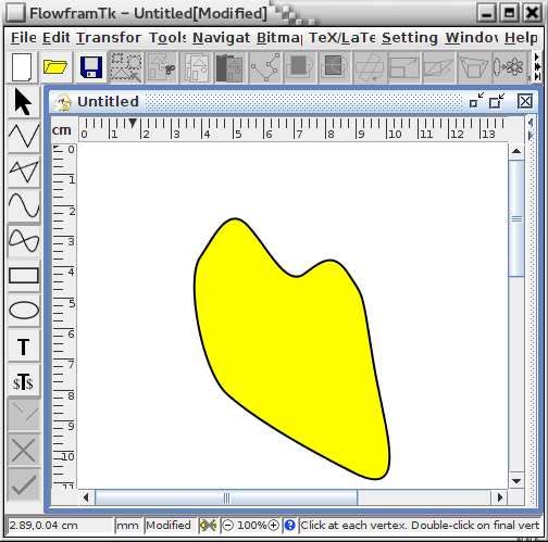
Note that the path attributes will only be set once the path has been completed. Whilst the path is under construction you will only see a draft version (see Figure 6.1). If you want a path with a mixture of line and curve segments, first construct a path with only one type of segment (e.g. lines), and then use the edit path function to convert the required segments.
|

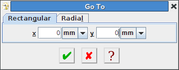
If you are unable to use the mouse, you can move the pointer using Navigate->Go To which will display the dialog box shown in Figure 6.2. Enter the x and y co-ordinates in the x and y fields if you are using a rectangular grid, or enter the angle and radius in the Angle and Radius fields, if you are using a radial grid. The function key F4 will emulate a single mouse click in construction mode.
 |
See also: